Wimo® | RFID diagnosis technology for concrete structures
Our structure diagnosis technology, which uses sensor-equipped RFID, is an innovative technology which utilizes RFID wireless technology to detect strain and steel corrosion producing environments inside structure, non-destructively and without direct contact.
Introduction
Why is structure diagnosis necessary?
There is a great deal of demand to move away from the past scrap & build approach to building structures. The introduction of asset management has brought with it an increased focus on maintenance and management technologies.
Concrete structures are an essential part of our daily lives, and, like people, they require regular health checks and continuous health monitoring to ensure long, productive lives.
Can't diagnosis be performed more easily?
Usual inspections of concrete structures are often performed through visual inspection.
Visual inspections are easy and inexpensive, but there are qualitative differences between individual inspectors.
Visual inspections are also incapable of detecting steel rebar corrosion caused by chloride attack, one of the three main causes of concrete structure deterioration.
We have developed the “Wimo® RFID diagnosis technology for concrete structures” for assessing structural integrity, led by the concepts of developing a technique which is “easy to use,” “non-destructive,” “quantitative,” and can be “used by anyone.”

Wimo® stands for
“Wireless Monitoring System.”
Wimo® and the Wimo® logo are registered trademarks of Taiheiyo Cement Corporation.
Systems
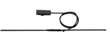
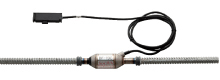
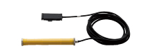
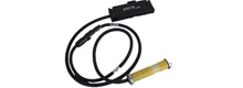
RFID Strain Measuring System
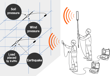
The results of various deterioration factors always act on structures in the form of strain. Wimo can non-destructively detect this deformation, regardless of the cause of the deterioration.
Features
- Strain measurement range of ±1000x10-6
- No additional on-site processing is required, making sensor installation easy.
- Special measurement device for easy measurement.
- RFID tag memory can store up to 6 measurements.
- Sensor position and data measurement position can be chosen as desired by changing the length of the cable between the sensor and the tag,
RFID Corrosion Environment Sensing System
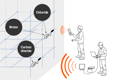
Damage from chloride attacks has a tremendous impact on structures. Corrosion occurring to sensors themselves is used to detect when corrosion factors, which corrodes rebar, penetrate into a structure.
Features
- Inspection can be carried out easily, without damaging the structure frame, as occurs when using core boring.
- Multiple sensors can be installed in order to identify locations and areas with a risk of rebar corrosion.
- Measurement results are color-coded, providing an intuitive view of corrosion risk.
- RFID tag memory can store up to 6 measurements.
- Sensor position and data measurement position can be chosen as desired by changing the length of the cable between the sensor and the tag,
Structure information management using i-CON Space
Utilizes an IC tag for easy management of information required for the maintenance operation and management of structures. Can be applied to recording of visual inspection results, traceability of concrete structures, etc.
Features
- Easy installation of IC tags inside concrete
- Each section managed using unique ID
- Use of inspection, traceability, and a variety of other systems
Overview and Features
OverviewSystem installed within concrete itself to wirelessly assess the status of structures
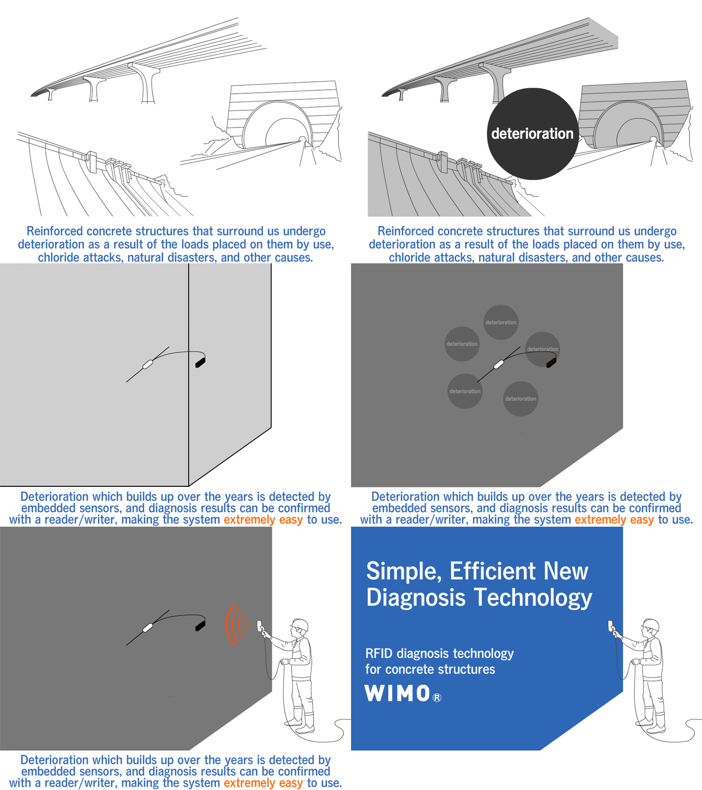
We have developed RFID Structure Diagnosis Technology (Wimo®), which combines sensor technology with the RFID technology widely used in electronic money, automatic ticket gates, and other systems.
RFID Structure Diagnosis Technology makes it possible to wirelessly measure the status of sensors embedded in concrete. By installing the RFID tag (the data communication unit) separately from the sensor, measurements at high locations and other hard-to-reach areas become easy.
Features

OverviewA system which measures strain in steel reinforced concrete structures.
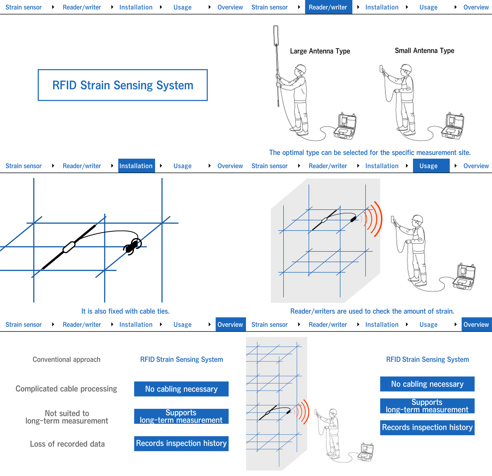
As concrete structures deteriorate, strain develops at various locations. Conventional strain measurement uses wired strain gauges or rebar meters connected to a data logger. However, deterioration of cables exposed from the structure makes long-term measurement difficult, and the cables also detract from the structure's appearance.
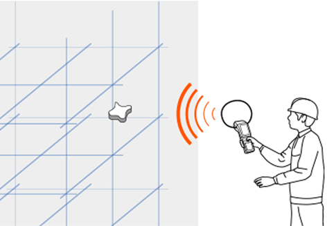
The RFID Strain Measuring System is a technology in which the communication unit (RFID tag) and sensor unit are installed inside the structure, and strain is measured when the sensor is activated by electromagnetic waves applied to the RFID tag from the structure's surface.
Anyone can easily take measurements with just a dedicated reader/writer and a PC. In addition, no cables or other components are exposed on the surface of the structure.
Features
- Strain measurement range of ±1000x10-6
- RFID tag memory can store up to 6 measurements.
- No additional on-site processing is required, making sensor installation easy.
- Special measurement device for easy measurement.
Installation
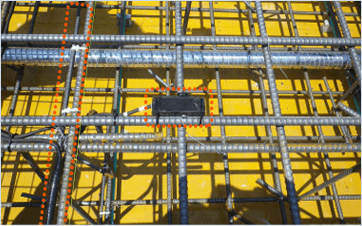
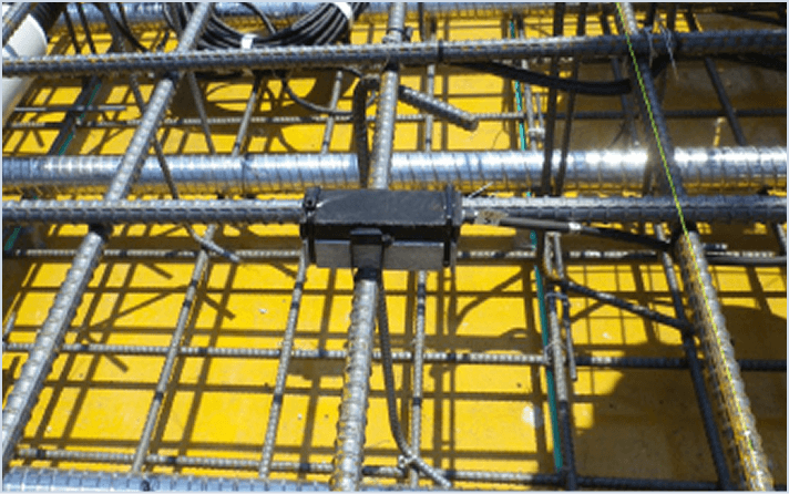
Step 1
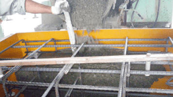
Align the sensor along the length of the rebar (primarily main reinforcement), and fix it with cable ties.
- Install the RFID tag at the intersection of multiple rebar, 5 cm or less from the surface of the concrete.
- Cast the concrete. When the mold is removed, there will be no exposed cable.
Measurement
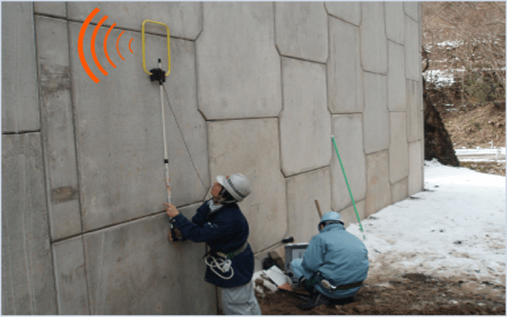
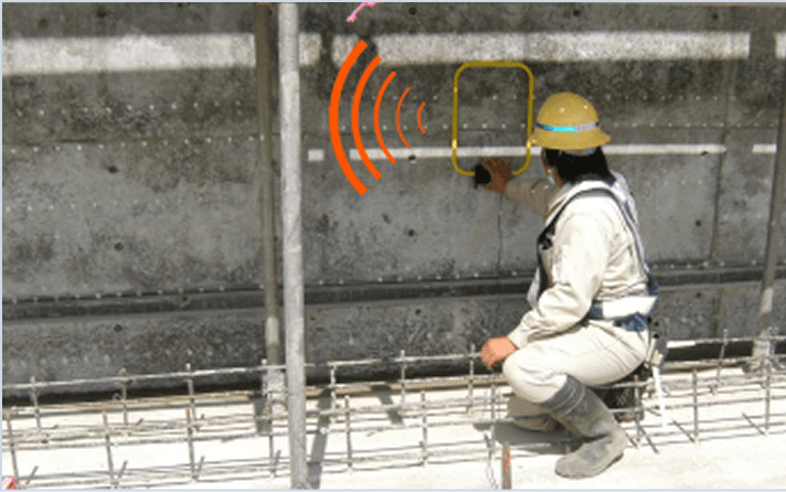
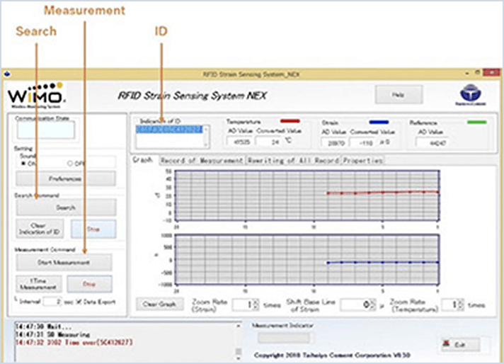
Step 1Search for the RFID tag
Press the search button on the reader/writer application, and move the antenna near where the embedded tag is located.
A notification sound will be played when the antenna passes over the tag, and the tag's unique number (ID) will be displayed.
Align the sensor along the length of the rebar (primarily main reinforcement), and fix it with cable ties.
Step 2Take a measurement
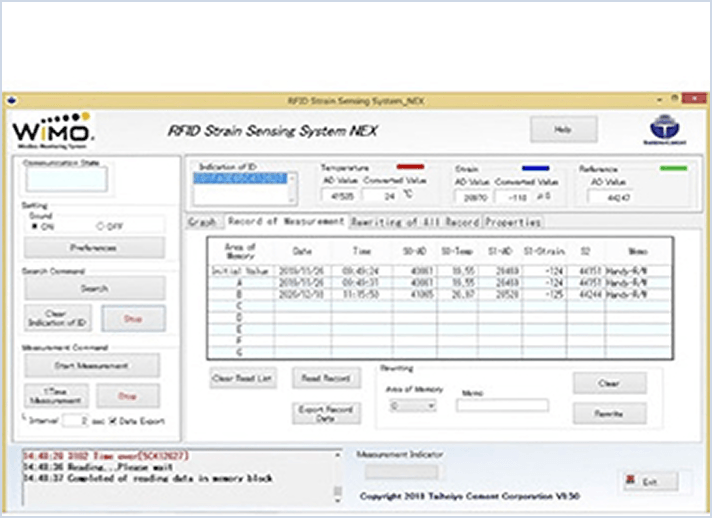
All you have to do to perform measurement is press the measure button to acquire strain data from the sensor.
- When past measurement history data, calibration factors, or other data are also stored on the tag, they will also be read in.
- Data can be stored in internal memory.
OverviewThis system is designed to detect any corrosion environment around the rebars within steel reinforced concrete structures.
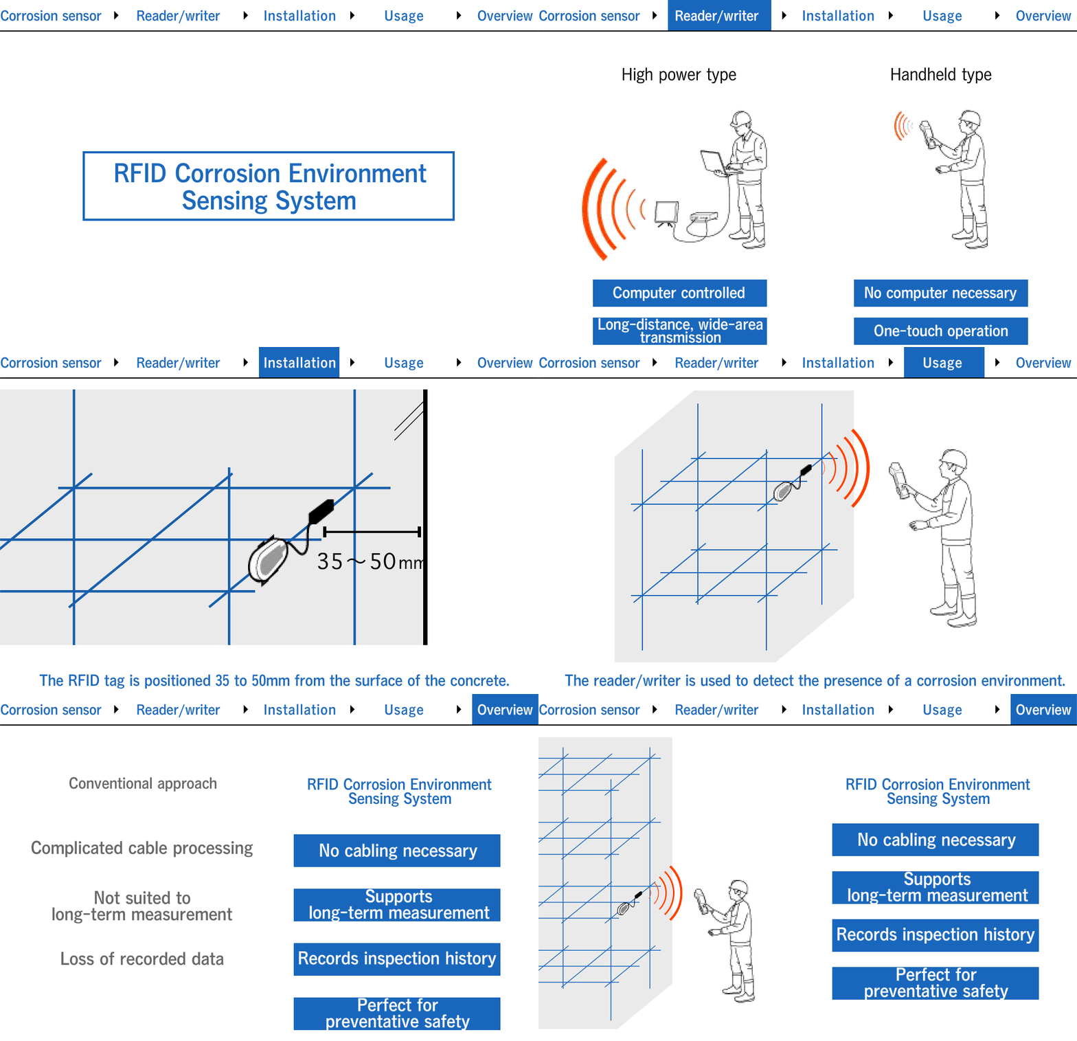
Damage from chloride attacks, one of the three main causes of concrete structure deterioration, is detected by observing the leakage of rust fluid from concrete surfaces. However, by the time this fluid has leaked out, rebar corrosion is already occurring at an accelerated rate, and major repairs may be required if countermeasures are not implemented immediately.
This system can detect corrosion environments around the rebar, such as salt water environments, in advance, helping prevent rebar corrosion before it can begin.
The system can detect not only salt water corrosion, but also corrosion types such as neutralization corrosion and chemical erosion.
Features
- Inspection can be carried out easily, without damaging the structure frame, as occurs when using core boring.
- Multiple sensors can be installed in order to identify locations and areas with a risk of rebar corrosion.
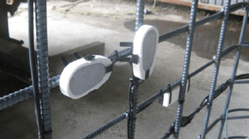
- Sensor position and data measurement position can be chosen as desired by changing the length of the cable between the sensor and the tag,
- Measurement results are color-coded, providing an intuitive view of corrosion risk.
Installation
Measurement
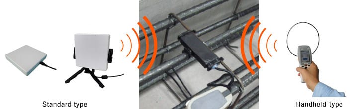
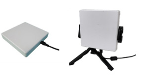
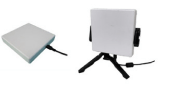
Two types of reader/writers are available for measuring: a standard type and a handheld type.
The high power reader/writer is used to perform measurements where the RFID tag is embedded deep within the concrete.
The handheld reader/writer is used to perform measurements where the RFID tag is covered by a smaller depth of concrete.
The high power reader/writer is used to perform measurements where the RFID tag is embedded deep within the concrete.
The handheld reader/writer is used to perform measurements where the RFID tag is covered by a smaller depth of concrete.
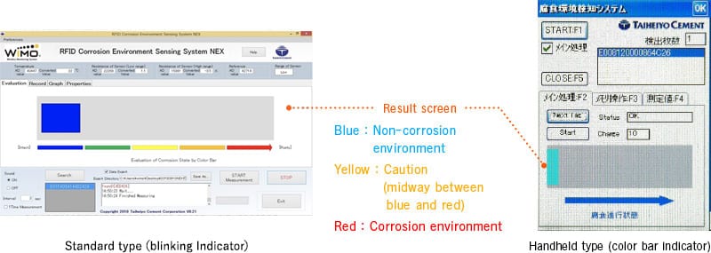
Start a search on the reader/writer application, and move the antenna near where the embedded tag is located.
A notification sound will be played when the antenna passes over the tag, and the tag's unique number (ID) will be displayed.
Start the process for measurement.
Measurement results are color-coded (with blinking indications and color bars) in each reader/writer application.
Result identification criteria have been developed based on the results of extensive experiments.
What is i-CON Spacer®?
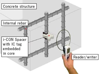
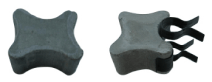
i-CON Spacer is a mortar spacer with built in IC tag.
By utilizing IC tags with unique IDs, i-CON Spacer enables management of information required for the maintenance operation and management of structures. Furthermore, by utilizing links with external systems and various types of management information, i-CON Spacer realizes an IoT (Internet of Things) for structures.
Overview
Similar to conventional mortar spacers, i-CON Spacer is used as a part for securing the thickness of concrete cover. It is affixed to rebar using a dedicated jig.

The name i-CON Spacer® was coined by combining the phrase “Information Concrete Spacer.”
i-CON Spacer® and the i-CON Spacer logo are registered trademarks of Taiheiyo Cement Corporation.
Installation
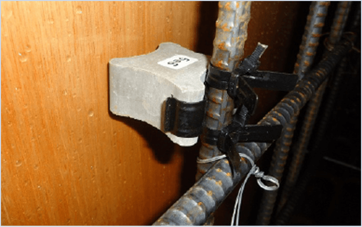
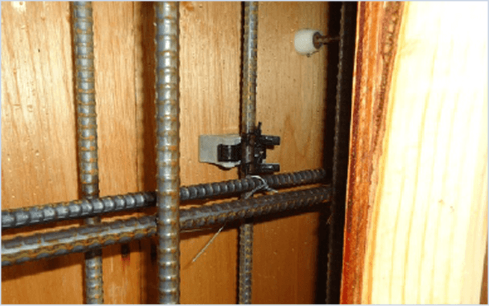
Affixed to rebar using a dedicated jig similar to conventional mortar spacers
With communication directionality, i-CON Spacer® must be installed appropriately.
Install so that the embedded IC tag is parallel to the concrete surface.
If it is affixed at a tag inclination of 30° or more, the tag may not be readable from outside.
Do not install within 15 cm of the concrete placing surface.
Measurement
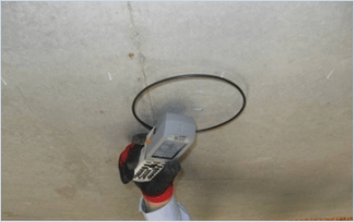
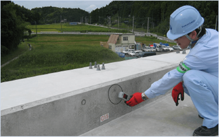
Handheld reader/writer facilitates measurement
Measurements are taken with a handheld reader/writer.
Keep the reader/writer antenna within 30 mm of the concrete surface when reading and writing.
Keep the reader/writer antenna within 30 mm of the concrete surface when reading and writing.
Using i-CON Spacer®
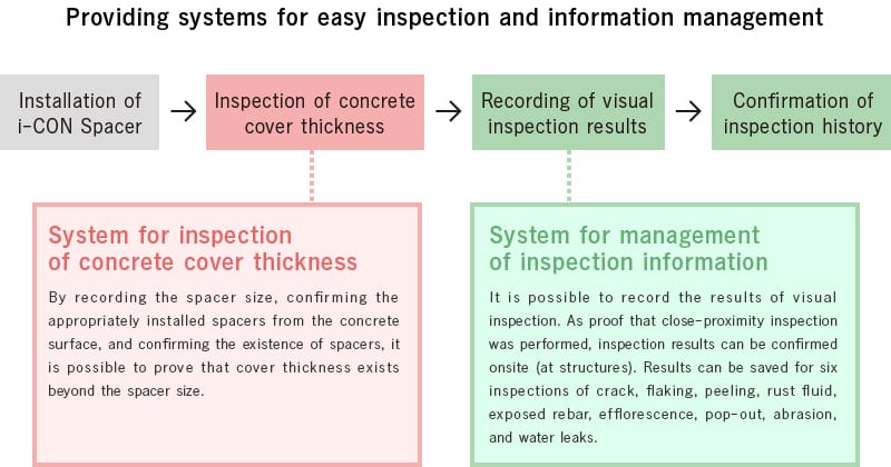
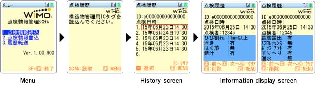
Cover thickness inspection system
Put a spacer size and check a spacer appropriately affixed from the surface of concrete.
Check the existence of spacer and thereby show that there is covering of more than the spacer size.
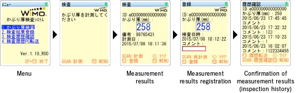
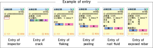
Inspection data management system
The system allows the results of visual inspection to be recorded. As proof of adjacent inspection, the results can be confirmed at the site.
Six results of crack, flaking, peeling, rust fluid, exposed rebar, efflorescence, popout, abrasion, and/or water leakage can be stored.
Providing diverse solutions for application to various systems
Management of concrete information
- Concrete name
- Mix proportion information, shipping information
- Specified strength, placing date, etc.
Relationship with drawings
- Identification ID assigned to each part
- Utilization in construction, management operation and maintenance through link with drawing information
- Management of position information for large structure
Links with various external systems
- ID and memory information can be output in CSV format
- Inspection information and construction information can be easily linked with map software and form management software
We can provide utilization systems and customization to meet your needs. Please contact us regarding your requests.
(Separate cost may be incurred for customization.)
Recoverability
Sensor

| Name | SSN-1390 | SSD-1390 | SSC-3725 | SSC-2290 |
|---|---|---|---|---|
| Image |
|
|
|
|
| Type | Standard type | High-durability type | Concrete strain type | Compact concrete strain type |
| StrainMeasurementRange | ±1000×10⁻⁶ | ±1000×10⁻⁶ | ±1000×10⁻⁶ | ±3000×10⁻⁶ |
| SensorLength(RebarLength) | 900 mm (Base rebar: D13 deformed bar) |
900 mm (Base rebar: D13 deformed bar) |
250 mm | 90 mm |
| Mass (excluding RFID tag) | 870 g | 1290 g | 600 g | 125 g |
| CableLength | Standard1m(canbechanged) | Standard1m(canbechanged) | Standard1m(canbechanged) | Standard1m(canbechanged) |
Reader/writer
| Name | Reader/writer |
|---|---|
| Image |
|
| Type | Standard type |
| Communication frequency | 13.56 MHz |
| Communication standard | Certifiedconformantwithtechnicalstandards |
| ExternalDimensions | 125(D)×125(W)×30(H)mm(includingantenna) |
| Weight | 220 g |
| DrivePower | USBBusPower(DC5V,Max150mA) |
Options
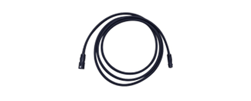
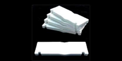
| Name | Extension cable | For the RFID tag |
|---|---|---|
| Image |
|
|
| Main unit specifications | Cable length: 1, 2, 4, 6, 9, 14 m (Cable diameter: φ6 mm) |
Ceramic Thickness: 10 mm |
Software
Operating environment
- OS
Windows Vista, Windows 7, Windows 8, Windows 8.1, and Windows 10
- Memory
1 GB or more
- HDD
200 MB or more
- Others
USB port or LAN port connection available
- Windows Vista, and Windows 7, Windows 8, Windows 8.1 and Windows 10 are trademarks or registered trademarks of Microsoft Corporation in the United States.
Sensor
| Name | RFID corrosion environment sensor |
|---|---|
| Image |
|
| Size | 90×50×15 mm |
| Mass (excluding RFID tag) | 175 g |
| Material | Ceramic |
| Strength | 400 N/mm² or more |
Reader/writer
| Name | Reader/writer | |
|---|---|---|
| Image |
|

|
| Type | Standard type | Handheld type |
| Description | 13.56MHz | Used when the tag cover is small. Only a button is needed to perform measurement. |
| Communication frequency | 13.56 MHz | 13.56 MHz |
| ExternalDimensions | 125(D)×125(W)×30(H)mm(includingantenna) |
Wireless standards:RFID
reader/writer Communication standard:ISO/IEC15693 :ISO/IEC18000-3(mode1)
|
| External dimensions | 125 (D) × 125 (W) × 30 (H) mm (including antenna) Weight: 220 g |
58×171×45 mm Grip section: 45 × 29 mm |
| PC connection | — | Bluetooth、USB |
| Drivingpower | Powered by USB bus power DC 5 V, max. 150 mA |
Lithium-ionbattery |
Options
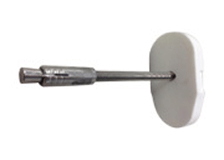
| Name | Extension cable |
For the sensor | For the RFID tag | For the RFID tag |
|---|---|---|---|---|
| Image |
|
|
|
|
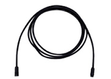
| Specifications | Cable length: 1, 2, 4, 6, 9, 14 m Cable diameter: φ5 mm |
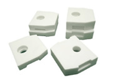
Ceramic Thickness: 10 mm, 15 mm |
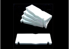
Ceramic Thickness: 10 mm |
Stainless steel Bolt outer diameter: M8 |
Software
Operating environment
- OS
Windows Vista, Windows 7, Windows 8, Windows 8.1, and Windows 10
- Memory
1 GB or more
- HDD
200 MB or more
- Others
USB port or LAN port connection available
- Windows Vista, and Windows 7, Windows 8, Windows 8.1 and Windows 10 are trademarks or registered trademarks of Microsoft Corporation in the United States.
Sensor
| Name | i-CON Spacer® |
|---|---|
| Image |
|
| Material | High-strengthmortar |
| Coverthickness(mm) | 30、35、40、45、50、60、70、80、90、100、110、120、130、140 mm |
| Supportedrebardiameter(mm) | 0、13、16、19、22、25、29、32、35、38、41、51 mm |
| Compressivestrength | 70MPaorgreater |
| Productdimensions(mm),weight(g) | Product dimensions and weight differ according to the supported cover thickness. e.g., Cover thickness: 35 mm / Outer size: 45 (H) × 50 (W) × 25 (D) mm / Weight: approx. 90 g |
Specifications of embedded IC tag
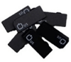
| Name | HF band | UHF band |
|---|---|---|
| Image |

|
|
| Frequencyband | 13.56 MHz | 920 MHz |
| Size | φ16×3 mm | 13×8×3 mm |
| Communication standard | ISO15693 | EPC Class1 Gen2 |
| Waterproofstandards | IP68 | IP68 |
| Operatingtemperatures | -25~85 °C | -25~85 °C |
| Memorycapacity | 110 byte | 64 byte |
Options
| Name | Reader/writer (Handheld type) |
|---|---|
| Image |

|
| Wireless standards | Inductivereader/writercommunicationequipmentWirelessfrequency:13.56MHz |
| Communication standard | ISO/IEC15693 ISO/IEC18000-3(mode1) |
| External dimensions | 58(W)×171(D)×45(H)mm/Glip:45(W)×29(H) |
| Weight(includingbatterypack) | 232g/255g(includingexternalantenna) |
| Datatransmissionmethod | Bluetooth、USB |
| Drivingpower | Lithium-ionbattery |
Application Example
Reinforced soil wall
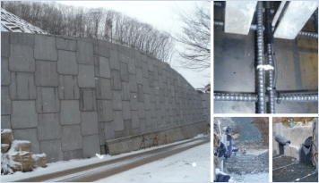
Objective
To confirm the safety of wall against torrential rain, ground freezing and expansion, earthquakes, etc.
Sensor
- In the concrete panel
Standard type
- Anchor bars
High Durability Type
Building structure (plant)
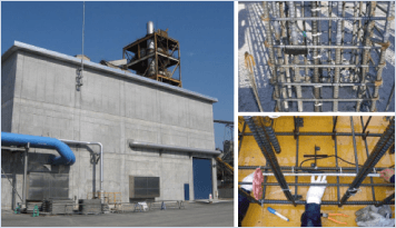
Objective
Confirmation of safety of columns supporting roof cranes and beams supporting heavy objects in factories
Sensor
- Beams
Standard type
Water purification plant
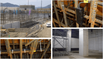
Objective
Measurement of strain caused by concrete volume changes and detection of cracking
Sensor
- Beams
Standard type
Water purification plant
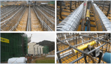
Objective
Measurement of strain caused by concrete volume changes and detection of cracking
Sensor
- Beams
Standard type
Other testing purposes
This technology can be used in various structures such as tunnels, floor slabs, and dams. Different rebar types can be special ordered.
Repair of bridge substructures
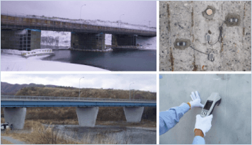
Objective
Verification of the effectiveness of corrosion protection (repair for salt damage) following patch repair as a measure against salt damage, and evaluation of the effectiveness of ongoing monitoring
Repair of river revetments
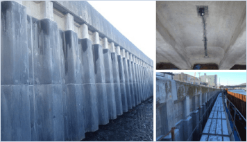
Objective
Verification of the effectiveness of repairs within Ductal panels installed to protect against salt damage, ice impact, and abrasion
Application in newly constructed building structures
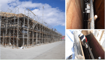
Objective
Verification of effectiveness of the technology for maintenance management in salt-damage environments
Application to the newly constructed PC bridge superstructures
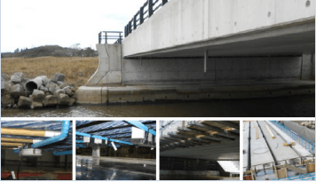
Objective
Verification of the effectiveness of the technology for maintenance management and preventive maintenance of PC structures in salt damage environments
Application to bridges
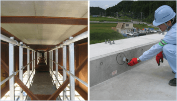
Objective
To check the cover thickness of floor slab bottom and
Wheel guard concrete
Sensor
Floor slab bottom, wheel guard unit
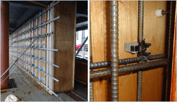
Application to architectural structure
Objective
To check the cover thickness of wall materials
Sensor
Walls of new architectural building
Download Pamphlet and Technical Data
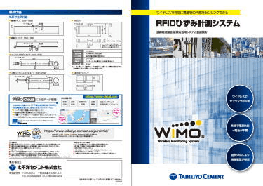
Ministry of Land, Infrastructure, Transport and Tourism: NETIS KT-100044
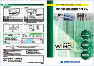
Ministry of Land, Infrastructure, Transport and Tourism: NETIS KT-110059
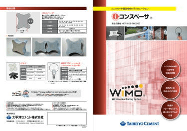
Ministry of Land, Infrastructure, Transport and Tourism: NETIS KT-160057
Inquiries
If you need any further information regarding the technology, please use this inquiry form to contact us.